诺斯罗普
诺斯罗普
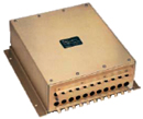
The console components of the Northrop Grumman Sperry Marine NAVIGUIDE 4000 Manual Ship Steering System let you customize or extend the Manual Ship Steering System as desired.
Steering Control Unit Contains all I/Os and the interface to the steering gear |
|
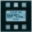
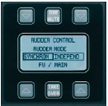
Steering Mode Selector Selects required steering mode |
|
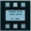
Steering Alarm Module Displays marine steering system alarms |
|
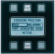
Marine Steering Position Selector Selects required steering stand |
|
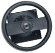
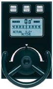
Follow-Up Handwheel 250 mm diameter |
|
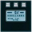
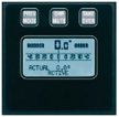
Follow-Up Interface/Display Unit Displays actual rudder angle and rudder order from a follow-up wheel |
|
SyncroHelm Wheel Control Unit Controls the main SyncroHelm follow-up hand wheel |
|
Dual Rudder Sync Selector Selects independent or synchronous rudder control |
|
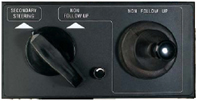
NFU Tiller Single NFU or dual NFU with overrride and/or VDR output |
|
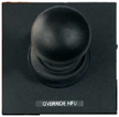
Marine Steering Mode Selector/NFU Tiller Selects secondary steering or main marine (NFU) and contains the NFU Tiller (Only for use on combination with an autopilot). |
|
Follow-Up Mini-Wheel/Display Unit Follow-up hand wheel with display of actual rudder angle and rudder order. |
|
Marine Steering Mode Selector Selects follow-up or non-follow-up modes |
The NAVIGUIDE 4000 Manual Ship Steering System is based on network solutions which easily can be modified or expand to requirements.
See below for an overview of the NAVIGUIDE 4000 performances:
| ENVIRONMENT | |
|---|---|
| Ambient temperature range (operation) | -15° C to +55° C |
| Ambient temperature range (storage) | -25° C to +70° C |
| Protection grade (installed) | IP32 to DIN 40050 |
| Magnetic clearance | 0.40m |
| Environmental testing in accordance with EN 60945 (IEC 945 +A1) | |
| Cable connection | Clamp-type terminals |
| Protection grade | IP32 to DIN 40050 |
| Dimensions | 151 mm Height, 392 mm Width, 425 mm Depth |
| Weight | 3 kg |
| Power requirements | 24 VDC (18 V to 36 V) |
| Maximum ripple conten | 4 V pp |
| Power consumption | 10 W max |
| Reverse polarity protection | Built-in |
| INPUTS | |
|---|---|
| Rudder order signal (follow-up hand wheel) | ±10 V ±120° max rudder angle potentionmeter resistance 2kW with center tap |
| Rudder angle feedback signal | ±10 V ±120° max rudder angle potentionmeter resistance 2kW with or without center tap |
| Speed input | 200 p/nm or NMEA 0183 |
| External system | ±10 V ±120° max rudder angle |
| Steering mode status | |
| Override status | |
| Mute | |
| Central alarm | NMEA 0183 |
OUTPUTS
| DC SOLENOID VALVES | |
|---|---|
| Outputs | Two for port, two for starboard (solid-state relays) |
| Voltage | 12 VDC to 110 VDC |
| Rating | 2.0 A max |
| Inputs | "Pump on” sense contact closure inputs |
| AC SOLENOID VALVES | |
|---|---|
| Outputs | Two for port, two for starboard (solid-state relays) |
| Voltage | 24 VAC to 230 VAC |
| Rating | 1.0 A max. |
| Inputs | "Pump on” sense contact closure inputs |
| PROPORTIONAL RUDDER ORDER/ ERROR | |
|---|---|
| Outputs | 80 mV/° to 350 mV/° (isolated) or 4 mA to 20 mA (isolated) |
| OUTPUTS AND INTERFACES | |
|---|---|
| Central alarm | NMEA 0183 |
| Voyage Data Recorder (VDR) | |
| CAN to IEC 61162-3 for bus interface units and additional steering control | |
| STATUS AND ALARM | |
|---|---|
| System alarm | Potential-free contacts |
| External system status | 115v AC, 0,5A /30v DL |
| Override alarm |
| POWER FAILURE ALARM | |
|---|---|
| Primary supply | Potential-free contacts |
| Backup supply |
Based on the control area network, the Ship Steering Control Network forms the backbone of the Control System, which is one of the first to implement the U.S. National Marine Electronics Association (NMEA) 2000 Data Communications standard.
Follow-Up and Non Follow-Up configurations are available for the NAVIGUIDE 4000. The different steering gear control system configurations are described as follows:
NFU Steering control is the cost-effective and safest means of steering control, but not very comfortable. The rudder moves as long as the NFU-Tiller is operated and stops, when the tiller is released or the rudder limits are reached.
The rudder follows the preset angle (rudder command) of the FU Handwheel and stops when this is reached. FU steering is a control of the rudder angle. It requires a Steering Control Unit (FU-amplifier) and a feedback unit in addition to the Handwheel. FU steering is more comfortable/user-friendly than NFU.
Dual Follow-up provides separated controls to each steering gear by means of two SCUs, each controlled by a separate potentiometer of the FU-Handwheel. A single failure only causes a loss of control of one steering gear. Dual FU is mandatory with certain classification societies or notations.
It is mandatory by IMO/SOLAS to have two electric steering gears that are completely independent, also with regards to the power supply. Usually, there are two separate steering gears, each with its own steering pump, solenoid valves etc.
The Rudder Angle Indication system is separate to the steering system and is for indication only. It is an IMO requirement to have this system independently from the steering control system. Rudder angle indication is required for each steering position and at the emergency steering position in the steering gear room. The different regulatory bodies vary on the requirements on the Rudder Angle Indicators (RAI). DNV requires a second, independent rudder angle indication system on the bridge. Panama Canal regulation requires large instruments (192x192mm minimum) on the bridge wings, visible for the pulling train operators and the IMO/MED (ISO 20673) requires the accuracy of the system to be above 1 degree. Northrop Grumman Sperry Marine rudder angle indicator systems are characterised by a diversity of different indicators, to fulfil the individual customer needs and regulations. The Rudder Angle Indicators are in different sizes, scales, type of installations and protection grades. In addition three-face rudder angle indicators with a 270° panoramic indication are offered. To meet IMO regulations for accuracy, Northrop Grumman Sperry Marine developed the Rudder Angle Calibrator (RAC). This is the central unit of the RAI system that provides NMEA outputs with the rudder angle, for Voyage Data Recorder and/or ECDIS/Conning Display. A total of 6 indicators can be connected to each RAC, including the feedback unit and each can be calibrated separately. Where there are more than 6 indicators, an additional Rudder Angle Calibrator is required.Rudder Angle Indicators for Every Need
Rudder Angle Calibrator
上一篇:诺斯罗普格鲁曼斯伯利sperry NAVIKNOT Multisensor Speed Log Series
下一篇:诺斯罗普格鲁曼斯伯利 sperry 斯伯利 通讯导航设备报价单查询 免费咨询电话021-22817852